Low-Voltage Enclosures for a Formula Electric Student Car
June 2025 — June 2026
Summary
Designed enclosures for low voltage boards and sensors, created calculator to maximize bolt spacing based on O-ring cross section, and designed dashboard for car.
This year I designed the low voltage enclosures and dashboard for our Formula Student electric car. This involved working with the electrical team and wire harness lead to figure out the size and stackup of each board, optimal wire harness positioning, and coordinating with our mechanical team on where the enclosures should be placed.
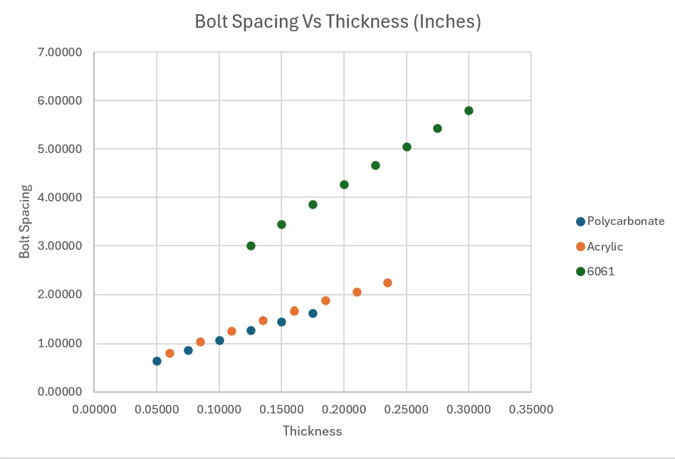
The main design choice I had to make that affected every enclosure was O-ring sizing, as well as selecting an appropriate groove to accommodate this O-ring cross section. I created a calculator to maximize the bolt spacing we could accomplish with a specific O-ring, and this informed our design choices and sizing for our enclosure lids and stiffeners. The calculator combined Parker Hannifin data on O-ring deformation force and compression percentage with beam bending to output a lid deflection, which ultimately drove our sealing capability.
Additionally, for each enclosure I ran a trade study on the placement of the enclosures on the car. The main things I considered were chassis integration, aero points, harness complexity, and accessibility. Figuring out the final position was a challenge, because we had to balance both access to my enclosures to troubleshoot our boards while also keeping the aero profile reasonable and not affecting our chassis setup.
Power Distribution Enclosure (PDBox)
The PDBox enclosure contains 3 boards vertically stacked and connected by board-to-board connectors. This box contains the Power Distribution Board, the Safety Board, and a splice board to connect the two. This enclosure is placed on the rear roof of the car right behind the driver to act as the heart of the low voltage system.
Rear Sensor Board Enclosure
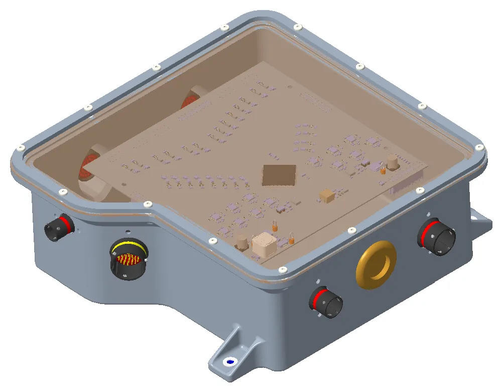
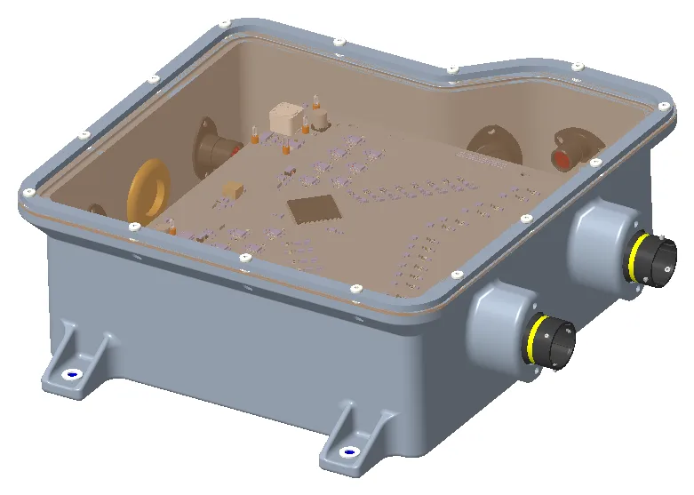
The Rear Sensor Board Enclosures each contain a rear sensor board, which powers and receives data from sensors. This board is also lid-mounted, which posed a challenge in designing this enclosure, because I did not want to overconstrain the board and strain the solder joints or cause bending on the board. This enclosure is placed on the rear sides of the car.
Front Sensor Board Enclosure
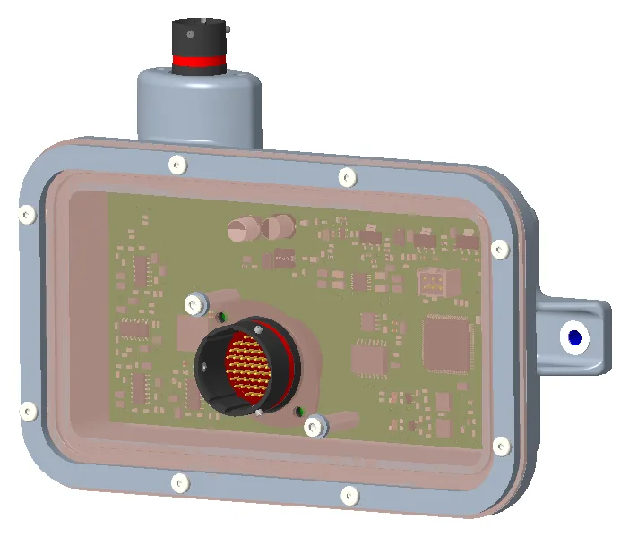
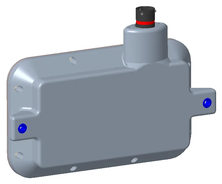
The front sensor board enclosure is similar to the rear, except that it is one enclosure with two boards. This design choice was made due to the addition of a damper cover on the front of the car, which let me hide the enclosure and eliminate aero drag compared to having the enclosures on the sides of the car in the front.
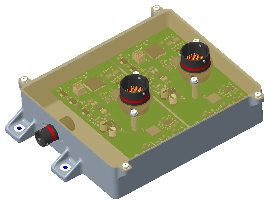
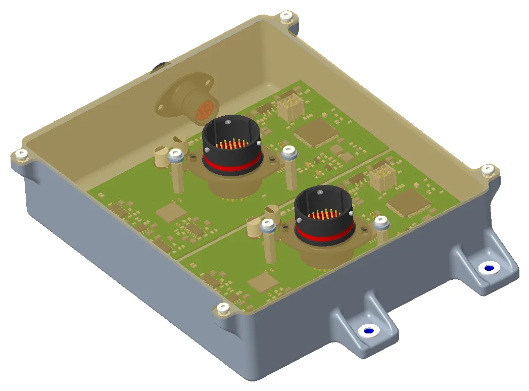
Low Voltage Battery Enclosure
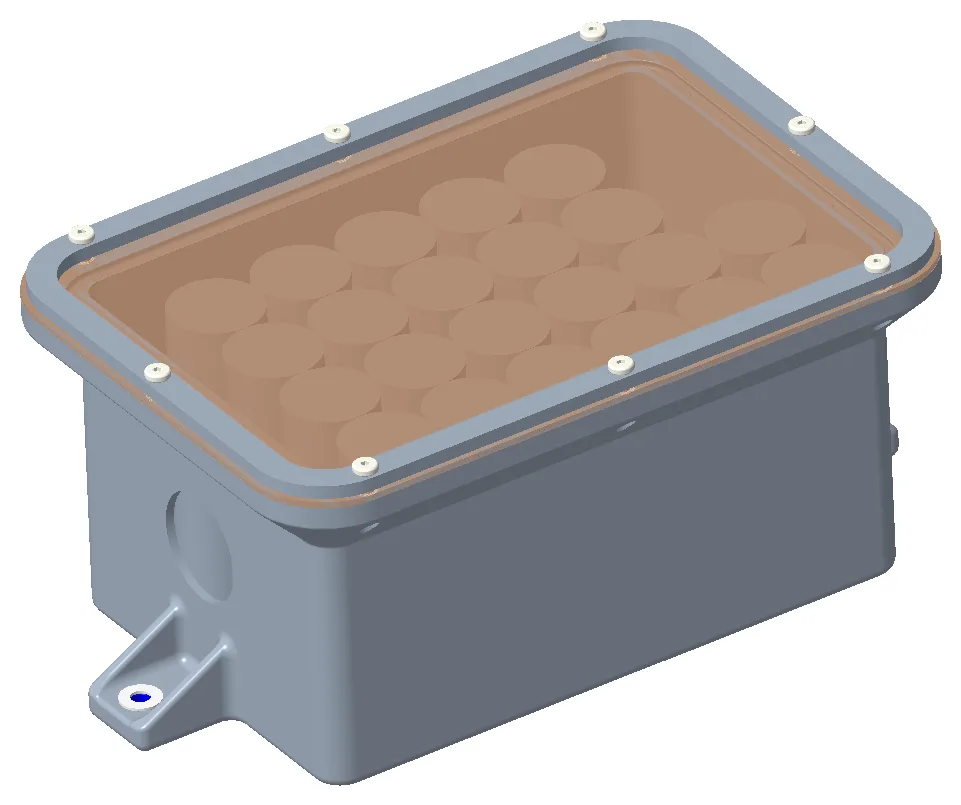
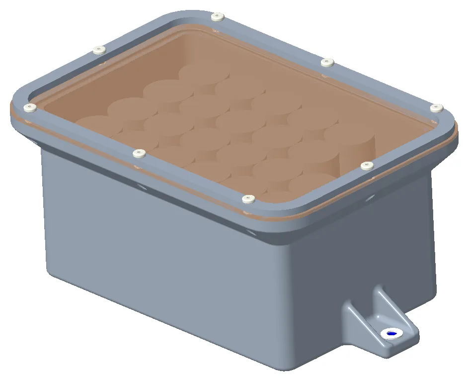
The Low Voltage Battery Enclosure contains our low voltage battery and is positioned underneath the seat and firewall. The main design challenges with this enclosure were finding a 3D-printable material that passed the fire-resistant rules and making the enclosure small enough to fit between the front panel of our firewall and our custom inverter.
IMU / ToF Enclosures
These enclosures each contain either an IMU or a time-of-flight sensor.
The IMU enclosures are mounted on the upright of our car near the brake rotors, so ensuring our enclosure wasn’t getting too hot was the main design challenge.
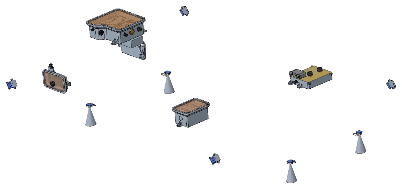
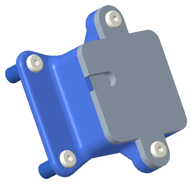
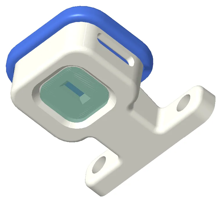
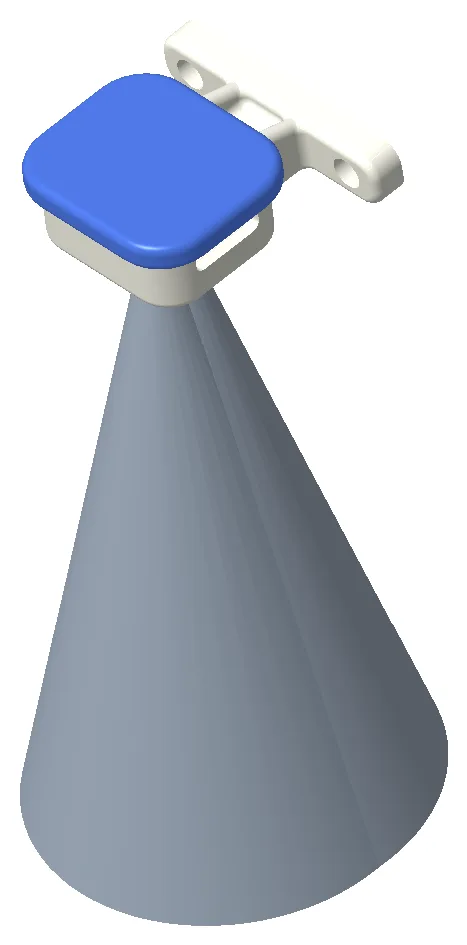
The ToF enclosures are mounted on the “corners” of the monocoque and need a clear line of sight to the ground within a cone. The cone in the image below represents the keep-out zone and guided how I placed the enclosure relative to other parts on the car.
Dashboard
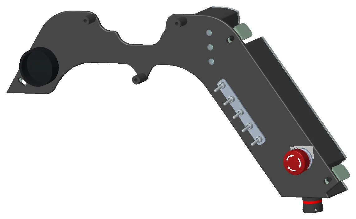
The dashboard contains a display, Switch Board, Fault LED Board, e-stop, and brake bias dial. Designing the enclosure around these boards meant figuring out how to fit them near each other while also keeping the profile of the enclosure within the front hoop of the car. I used a 3D scanner to generate a point cloud to help me fit the dashboard to our car and prevent any gaps.
Additionally, because this part has a very high width-to-thickness ratio, I added ribs to stiffen the enclosure and prevent unwanted bending when our driver uses any switches or bumps into the dashboard.
VNAV Enclosure
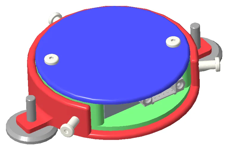
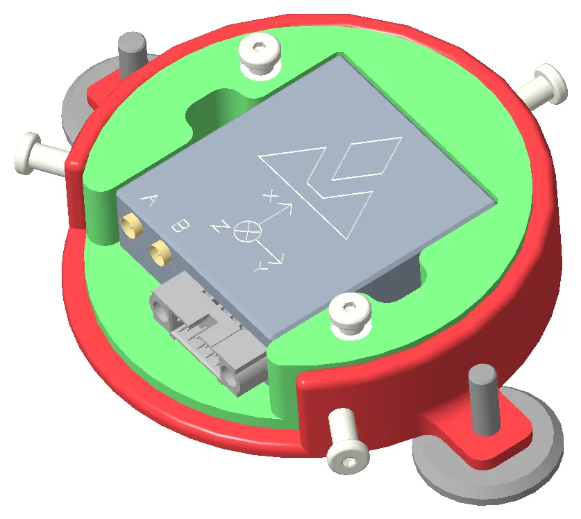
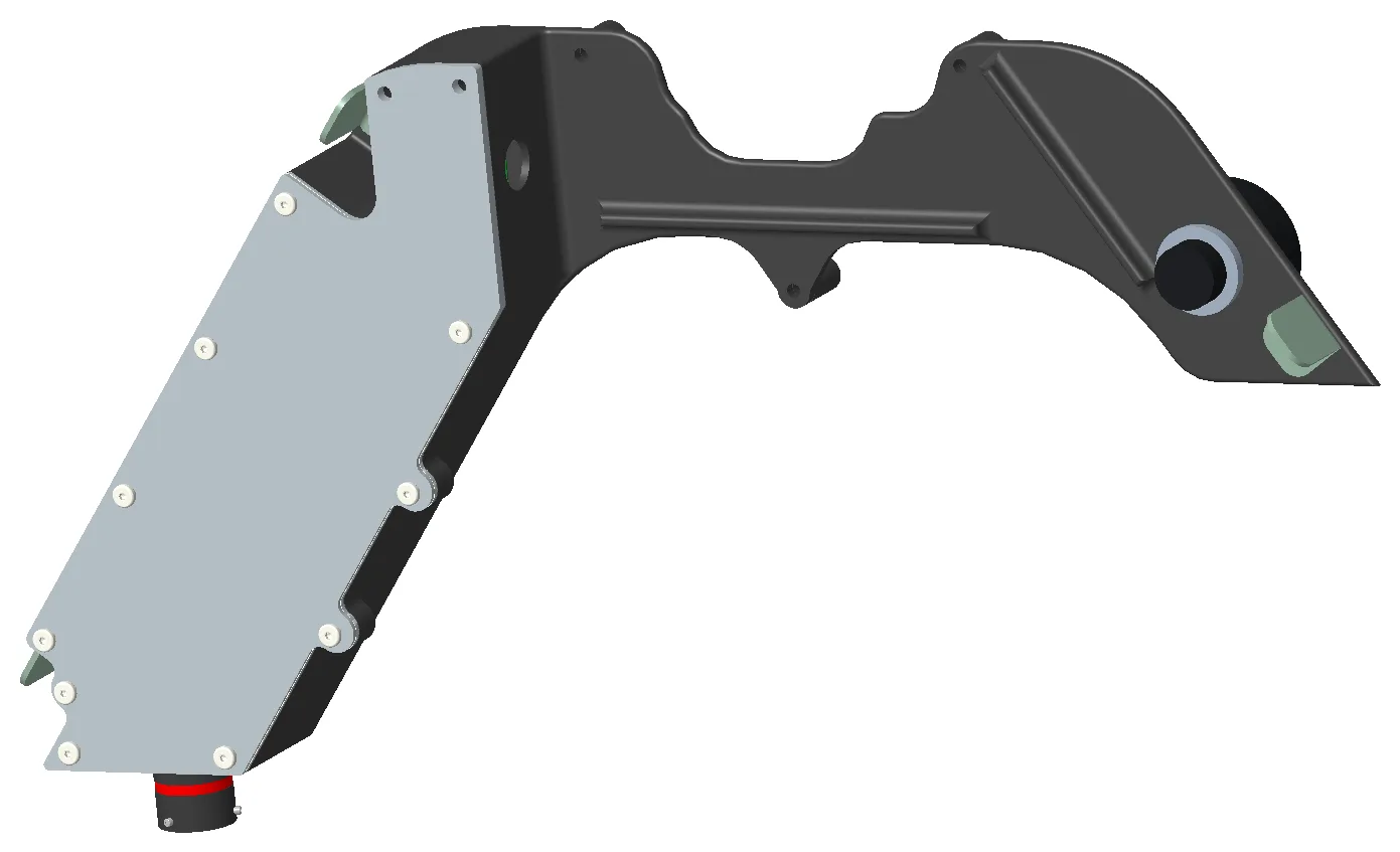
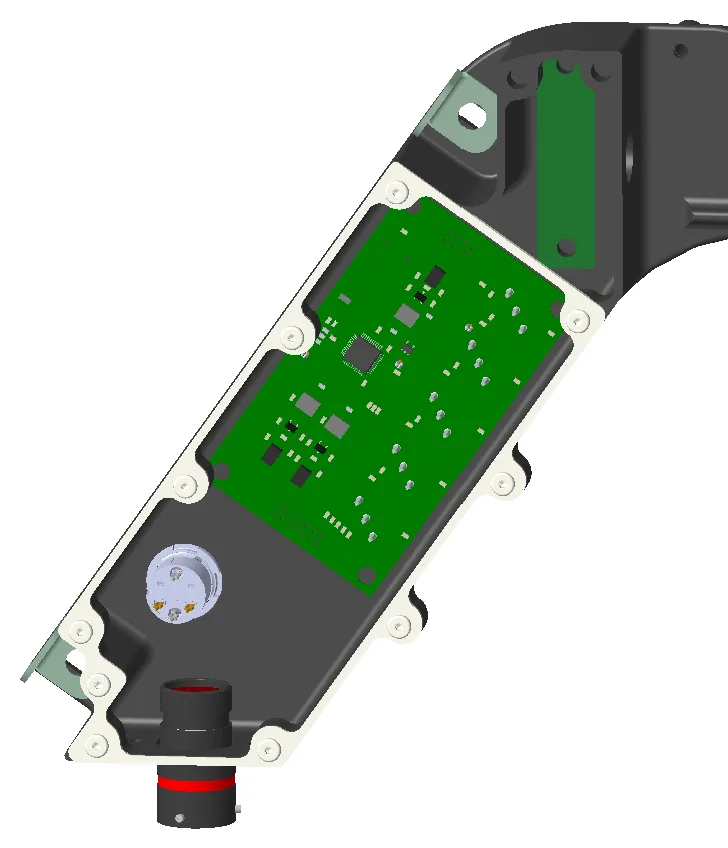
The VNAV Enclosure contains our VNAV sensor, which helps us track our car and is incredibly important to our DAQA team. The main features of this design are the mounting dowels to keep the X-Y position of the sensor repeatable, and a series of screws on the side of the enclosure to allow for adjustable rotation of the sensor to help us align it with antennas on the front and rear of the car.