Hello! I'm Charles! I love photography — honestly, I like to take pictures of everything: nature, cars, portraits, landscapes. I think my favorite things to shoot are landscapes and abstract photos! My current camera is an Olympus E-M1 Mark III.
LOBBY
Welcome to the Gallery
Welcome to my gallery of the work I'm most proud of! Thank you for stopping by and checking it out! To the left is my photography, and to the right is the mechanical engineering work that I've done for the various clubs and companies I've worked for. I hope you enjoy!
PHOTOGRAPHY ALLEY
ENGINEERING HALL
Garmin Aviation Mechanical Engineering Intern
Designed servo test fixtures for DO-160 environmental certification, redesigned the factory's dyno test fixtures to fix recurring clamp, corrosion, and bearing failures, and designed fixtures and assembly tools to support production.
Job
SolidWorks
FEA
Mechanical Design
GD&T
DFM
DO-160
Mechanical Engineering Intern at Oceaneering
Modeled wire harnesses for a large-scale ROV's telemetry and propulsion systems, designed and validated sensor brackets, and wrote a VBA tool that cut part-search time by 96%.
Job
FEA
Cabling
SolidWorks
Mechanical Design
DFM
Low-Voltage Enclosures for a Formula Electric Student Car
Designed enclosures for low voltage boards and sensors, created calculator to maximize bolt spacing based on O-ring cross section, and designed dashboard for car.
Creo
DFM
Waterproofing
SLS Printing
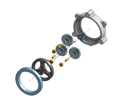
3D Printed Planetary Gearbox
5:1 stackable planetary gearbox designed in Onshape and 3D printed for an Underwater Robotics manipulator. I chose to design a planetary gearbox because it allowed us to create a very small gearbox, since we were limited in space diametrically.
Onshape
3D Printed
Gearbox Design
EXIT / CONTACT
That's all folks!
Thanks for visiting! If you are interested in hiring me or learning more about my projects, feel free to reach out!
Disclaimer: The images below were approved by my manager for public use.
Servo Test Fixtures
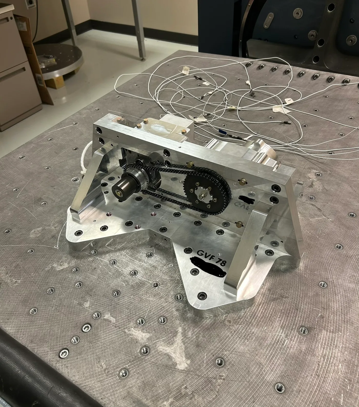
My Vibration Fixture On Vibe Table
My first project was designing fixtures for servo testing to certify them in DO-160 testing. I was tasked with designing fixtures to support sections 4, 5, 7, and 8 as well as additional electrically related sections. Sections 4 and 5 are heat and humidity while 7 and 8 are shock and vibration. I learned a lot about how these tests are run and also helped run some of the vibration lab tests and heat tests.
I ended up designing 1 main metal fixture to support vibration and shock testing, and then designed 2 derivative fixtures out of Delrin for heat, humidity, and EMI. I chose to make separate fixtures for sections 4 and 5 because I did not want my fixture to act as a thermal reservoir or have induced magnetic fields during EMI tests.
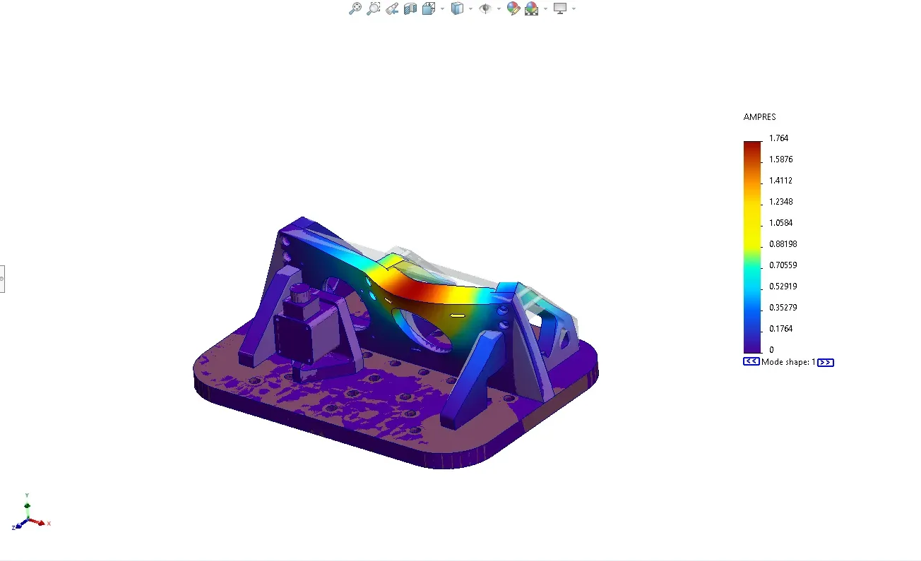
Additionally, I ran a frequency analysis in SolidWorks to ensure that my fixture was not adding additional resonance to the system below the test curve, and also validated previous engineering choices in older fixtures. I later tested my vibration fixture on our vibration tables to check the accuracy of my resonance analysis. I found that my fixture followed the predicted modes closely, with the first mode being 1625 Hz in the simulation and 1620 Hz on the vibe table.

Frequency Analysis Of S7/S8 FixtureMode Shape Animation
Dyno Test Fixture Redesign
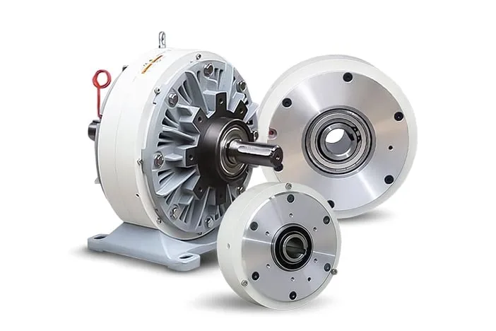
Particle Brake Example
I also redesigned the dyno fixtures in our factory with SolidWorks to improve the ergonomics and reliability. The main problems with the previous design were: technicians were breaking handles, clamps were failing constantly, there were corrosion problems, and bearings were shifting out of their mounts.
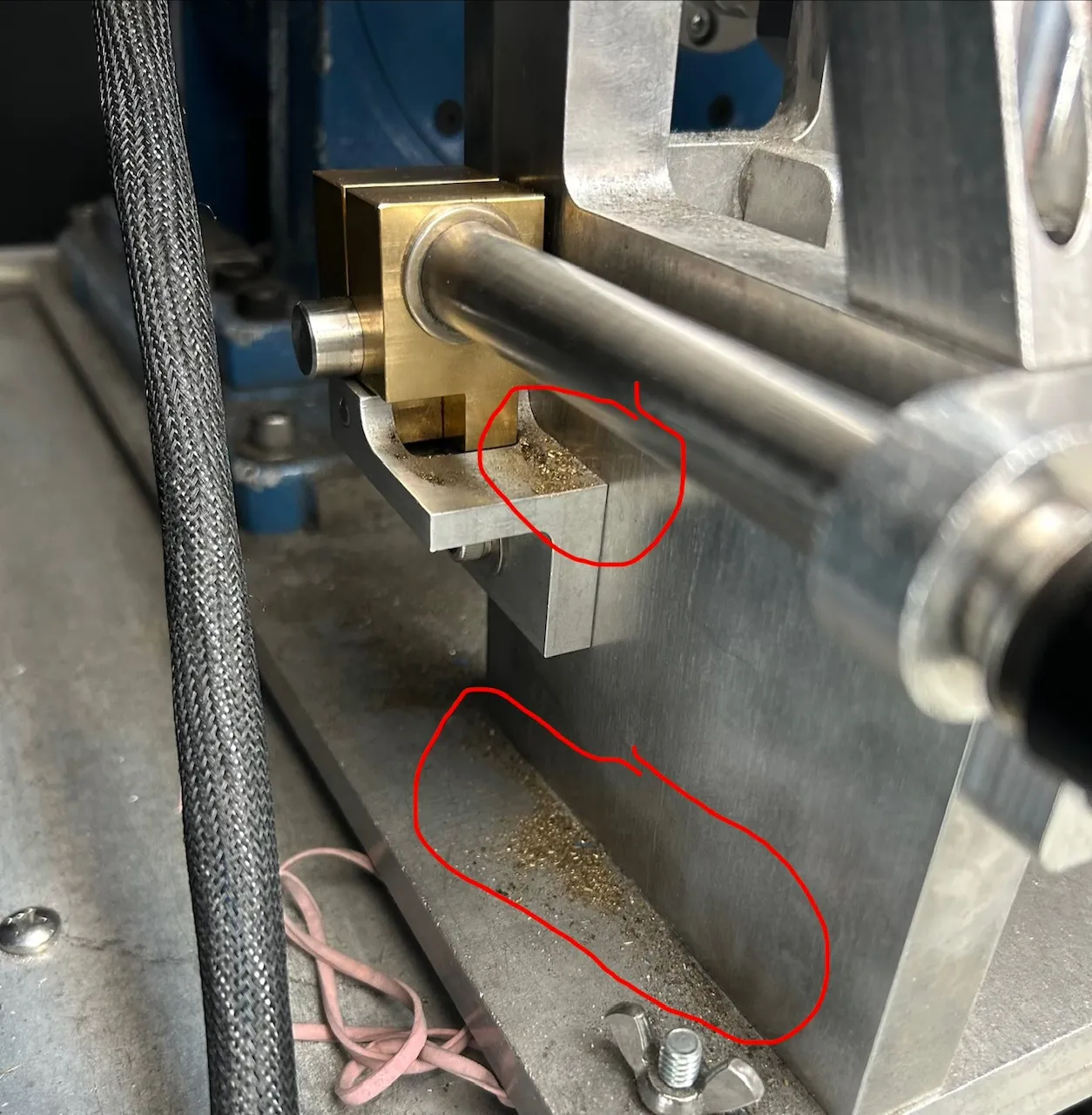
The first parts I updated were the clamps. These parts were failing weekly and occasionally daily due to the threads shearing off from wear and overload. In fact, underneath the clamps we were able to find piles of brass dust from the threads wearing down over time. To fix this problem, I changed the clamp material from brass to an aluminum bronze so that we would get a stronger material while still keeping the friction low. I also added helicoils to the threaded parts so that we could reduce wear. I validated these changes by doing hand calcs and proof loading them to see the change in yield.
Pile Of Brass Filings From Clamps
For the corrosion and bearing problems, I solved these by designing “rain covers” that sit over the parts with the most corrosion to direct the water away. I believed this was a better change than replacing all parts that could corrode with a different material, because the covers eliminated the problem and were much cheaper and easier to install. For the bearing problem, the previous design had no constraints, so over time the bearings would slip out of their mounts. To fix this, I added a shoulder and snap ring to retain the bearings and prevent them from walking away.
Secondary Operation Fixture Design
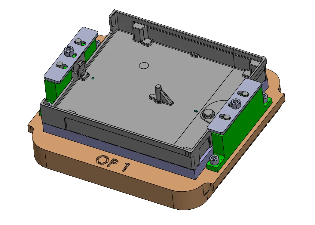
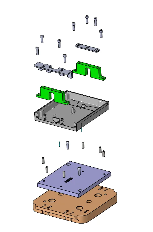
Secondary Operation Fixture — OP 1Secondary Operation Fixture, Exploded
I designed a set of 4 fixtures to help support our casting suppliers with secondary operations. I worked with our machine shop lead to determine part orientations and which operations to machine in each setup. This helped balance the workload evenly across human and machine time. The design of these fixtures involved figuring out how to hold each part and leave clearance for tools to complete their operation. Each fixture uses a set of 2 clamps that are shared between the 4 configurations to help minimize unique parts, and alignment pins are used to locate both the cast parts and each fixture part relative to the machine.
One thing I learned a lot about in this project was interacting with outside suppliers to figure out their machine capabilities and adapting my designs to fit their processes.
GSA 28 CMM Data Analysis and Inspection Gauge Design
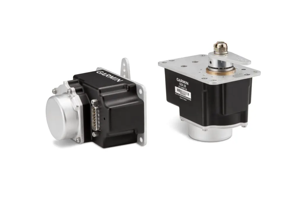
GSA 28 Autopilot Servo
A recurring issue was parts being shipped in from our suppliers and our inspection team finding them to be out of tolerance. Specifically, a large percentage of the GSA 28 output shafts were coming in out of tolerance. I used Excel and over 12 CMM reports to create visualizations of our tolerance zones overlaid with the measurement data to find patterns and potential causes for the failed parts. With this, I was able to visualize and calculate how much higher our yield rate would be if we increased the tolerance zone.
Additionally, I designed an inspection gauge to check the tolerances on the GSA 28 shaft. I did a tolerance analysis to figure out what dimensions and tolerances to use in my gauge to be able to catch the bounds of the parts. This taught me a lot about GD&T and how a tolerance stackup builds in gearboxes.
Testing Activities
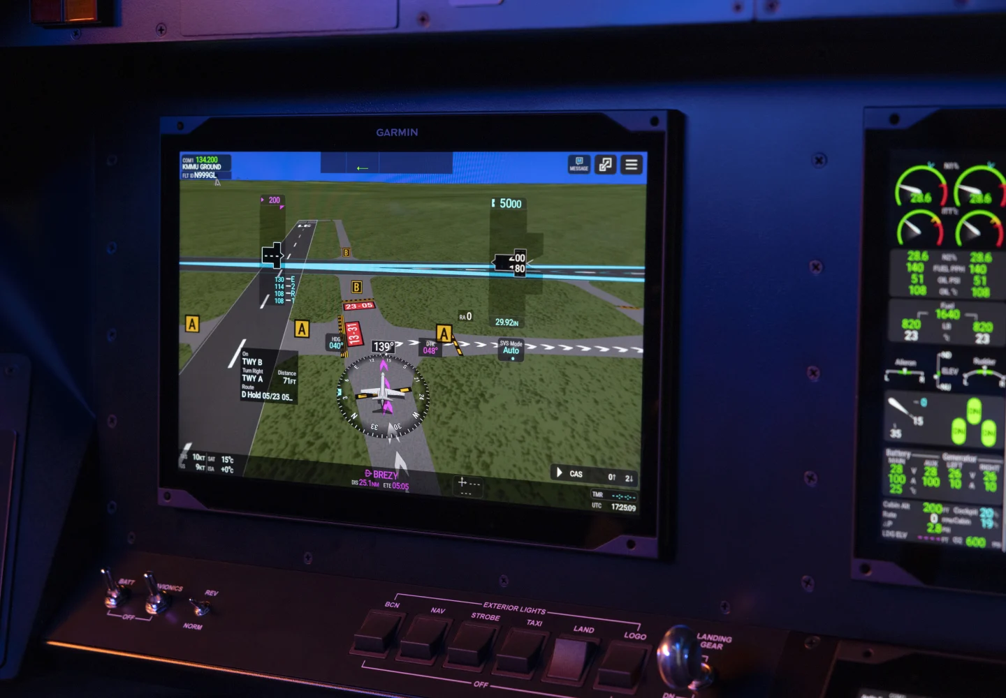
G3000 Prime 14" Display
I ran TSO cold testing on Garmin’s G3000 Prime 14” and 7” displays to validate a new adhesive used in the display stackup. To do this, I programmed a Tenney chamber to follow the test temperature profile documented in DO-160 and then inspected each display to find defects. I compared this with an ambient report to see changes caused by the cold test.
I also conducted ripple testing on our 14” and 7” displays at hot, cold, and ambient temperatures to ensure the displays still functioned correctly after hot and cold baking. I accomplished this by bringing the displays to a steady temperature and then pressing on the displays in a grid to validate that no ripples or distortions were forming in the screen.
In addition to testing them, I also disassembled each display to swap out their power modules, which taught me a lot about how the displays are put together.
Miscellaneous Fixture And Gauge Design
Throughout the summer, I also supported smaller efforts to design tools and gauges to help the assembly or inspection of various products.
Go/No-Go Gauge Design
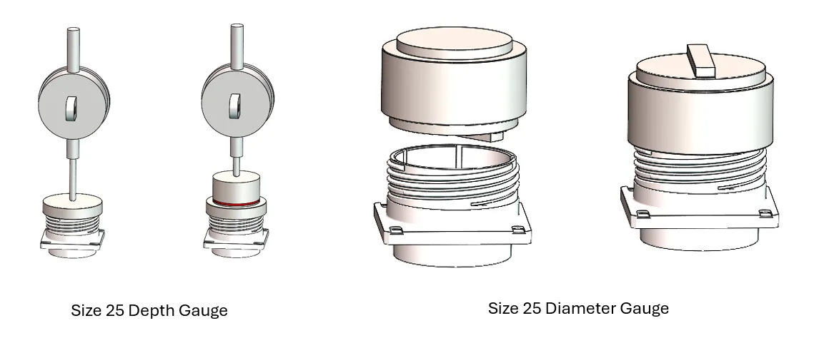
I designed a Go/No-Go Gauge for 4 different sizes of circular connectors to check diameter and depth. This design involved analyzing the engineering drawings for the connectors and figuring out what the upper and lower bounds of each diameter and depth were and then using those to drive the dimensions of the gauges. These bounds help make sure the go gauge only works with parts within tolerance and the no-go gauge correctly eliminates bad parts. I also created engineering drawings to release each of these parts to our machine shop for manufacturing and inspection.
I designed and 3D printed an assembly tool that helped assemble a new controller. This was driven by a need to guide technicians with a tool that was intuitive to use without excessive written instructions. This tool used the features on each part to help align the tool to the assembly.
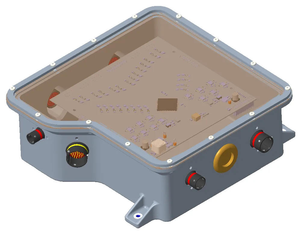
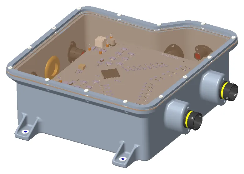
This year I designed the low voltage enclosures and dashboard for our Formula Student electric car. This involved working with the electrical team and wire harness lead to figure out the size and stackup of each board, optimal wire harness positioning, and coordinating with our mechanical team on where the enclosures should be placed.
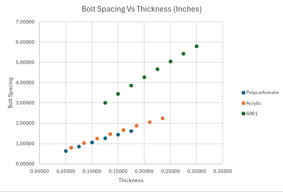
Maximum Bolt Spacing vs. Lid Thickness by Material
The main design choice I had to make that affected every enclosure was O-ring sizing, as well as selecting an appropriate groove to accommodate this O-ring cross section. I created a calculator to maximize the bolt spacing we could accomplish with a specific O-ring, and this informed our design choices and sizing for our enclosure lids and stiffeners. The calculator combined Parker Hannifin data on O-ring deformation force and compression percentage with beam bending to output a lid deflection, which ultimately drove our sealing capability.
Additionally, for each enclosure I ran a trade study on the placement of the enclosures on the car. The main things I considered were chassis integration, aero points, harness complexity, and accessibility. Figuring out the final position was a challenge, because we had to balance both access to my enclosures to troubleshoot our boards while also keeping the aero profile reasonable and not affecting our chassis setup.
Power Distribution Enclosure (PDBox)
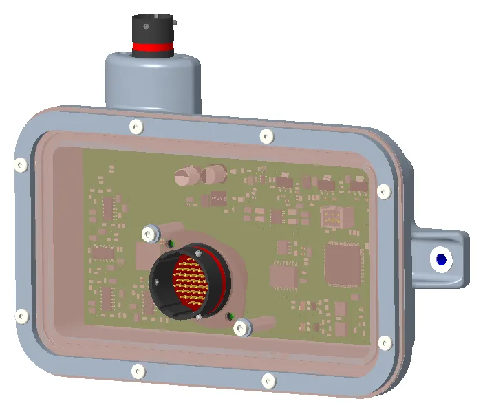
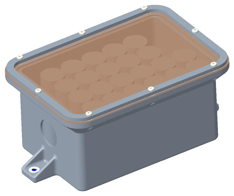
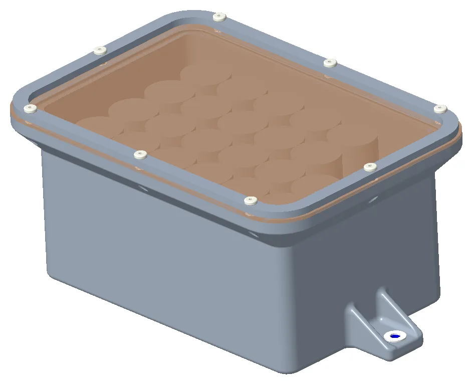
The PDBox enclosure contains 3 boards vertically stacked and connected by board-to-board connectors. This box contains the Power Distribution Board, the Safety Board, and a splice board to connect the two. This enclosure is placed on the rear roof of the car right behind the driver to act as the heart of the low voltage system.
PDBox — Connector SidePDBox — Mounting Side
Rear Sensor Board Enclosure
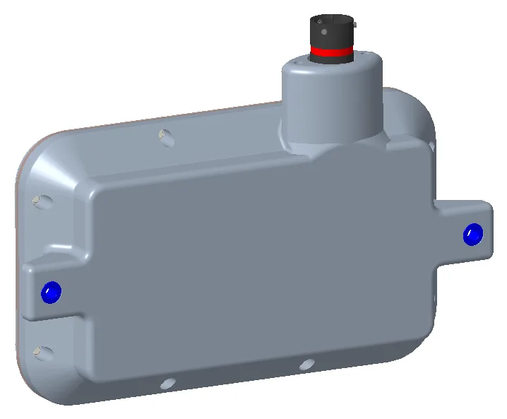
The Rear Sensor Board Enclosures each contain a rear sensor board, which powers and receives data from sensors. This board is also lid-mounted, which posed a challenge in designing this enclosure, because I did not want to overconstrain the board and strain the solder joints or cause bending on the board. This enclosure is placed on the rear sides of the car.
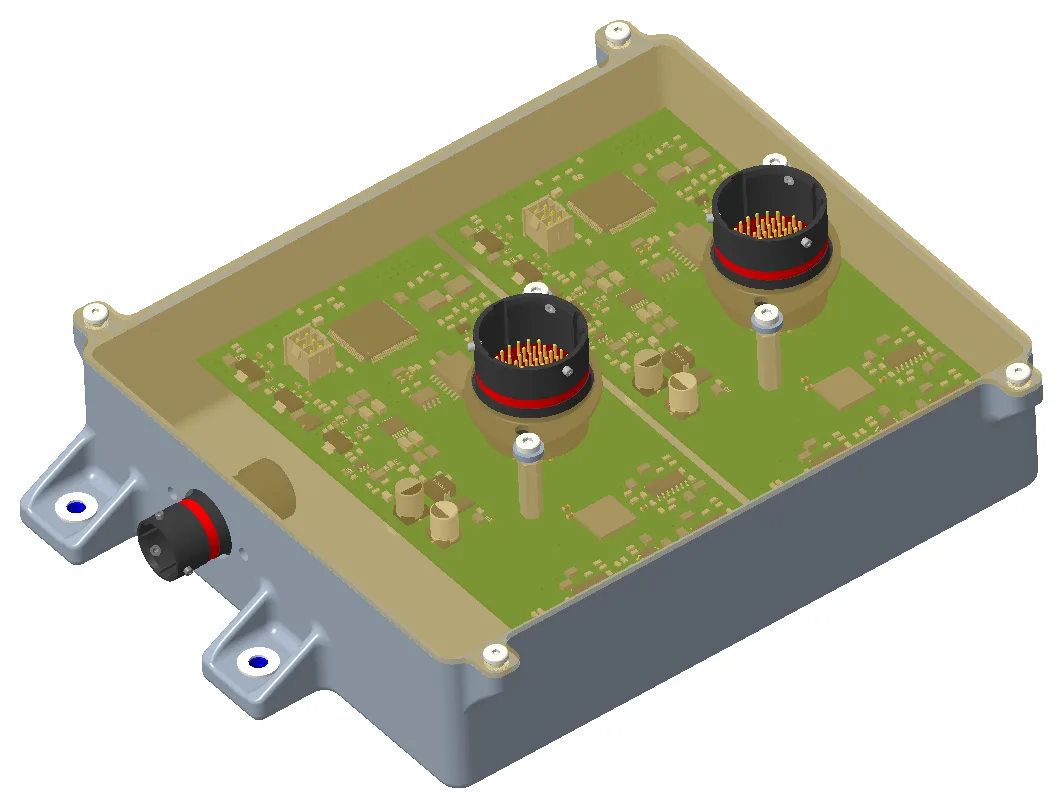
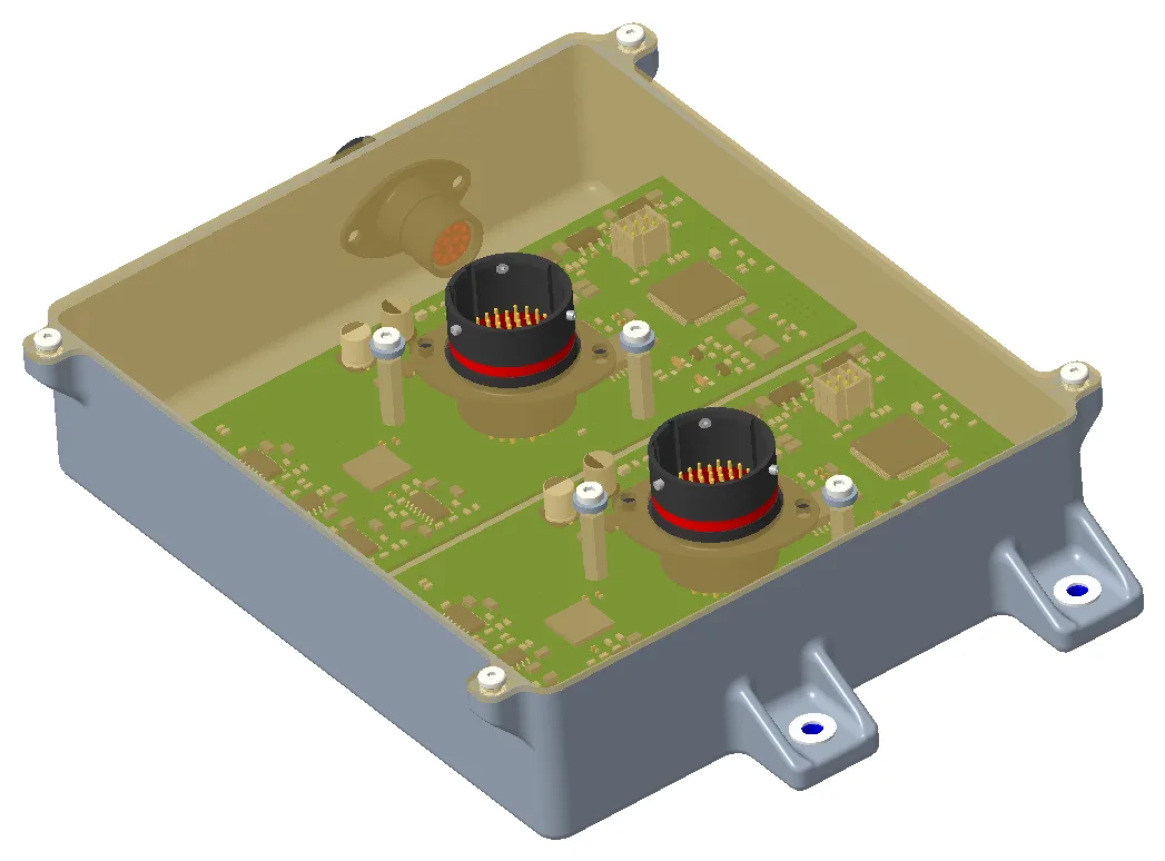
The front sensor board enclosure is similar to the rear, except that it is one enclosure with two boards. This design choice was made due to the addition of a damper cover on the front of the car, which let me hide the enclosure and eliminate aero drag compared to having the enclosures on the sides of the car in the front.
Front Sensor Board EnclosureFront Sensor Board Enclosure, Alternate View
Low Voltage Battery Enclosure
The Low Voltage Battery Enclosure contains our low voltage battery and is positioned underneath the seat and firewall. The main design challenges with this enclosure were finding a 3D-printable material that passed the fire-resistant rules and making the enclosure small enough to fit between the front panel of our firewall and our custom inverter.
Low Voltage Battery EnclosureLow Voltage Battery Enclosure, Alternate View
IMU / ToF Enclosures
These enclosures each contain either an IMU or a time-of-flight sensor.
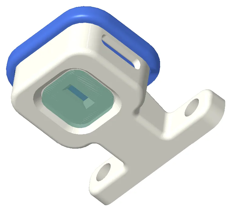
The IMU enclosures are mounted on the upright of our car near the brake rotors, so ensuring our enclosure wasn’t getting too hot was the main design challenge.
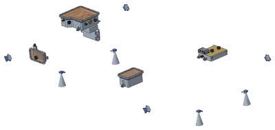
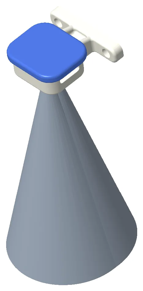
The ToF enclosures are mounted on the “corners” of the monocoque and need a clear line of sight to the ground within a cone. The cone in the image below represents the keep-out zone and guided how I placed the enclosure relative to other parts on the car.
IMU EnclosureToF Enclosure
ToF Sensor Field of View
Dashboard
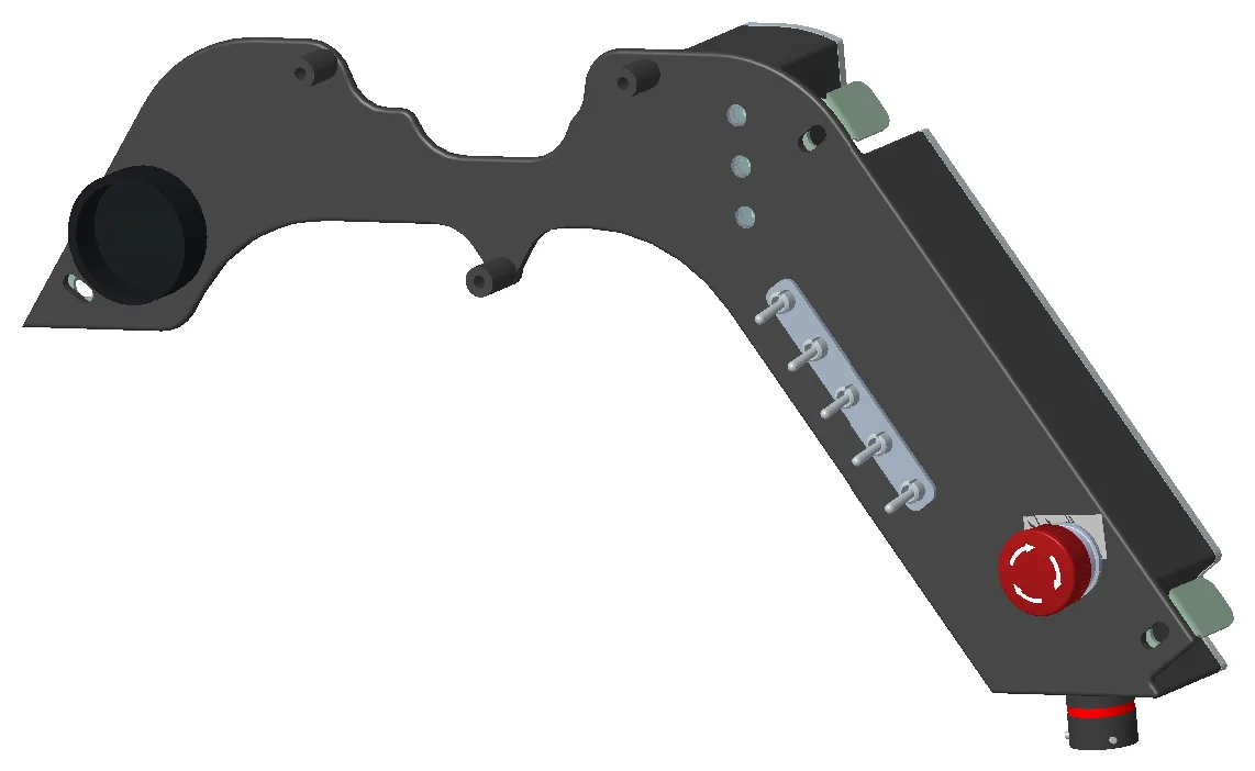
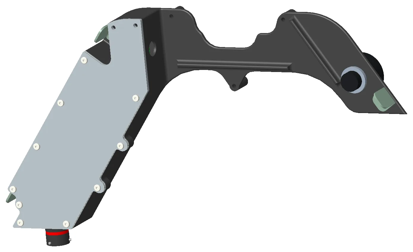
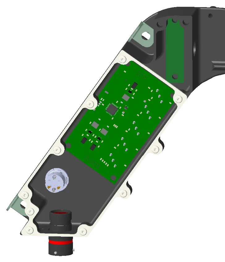
The dashboard contains a display, Switch Board, Fault LED Board, e-stop, and brake bias dial. Designing the enclosure around these boards meant figuring out how to fit them near each other while also keeping the profile of the enclosure within the front hoop of the car. I used a 3D scanner to generate a point cloud to help me fit the dashboard to our car and prevent any gaps.
Additionally, because this part has a very high width-to-thickness ratio, I added ribs to stiffen the enclosure and prevent unwanted bending when our driver uses any switches or bumps into the dashboard.
Dashboard — Driver SideDashboard — Rear Cover
Dashboard Electronics3D Scan Alignment Check
VNAV Enclosure
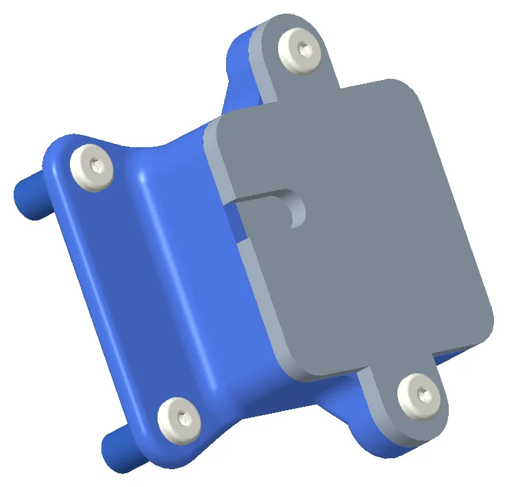
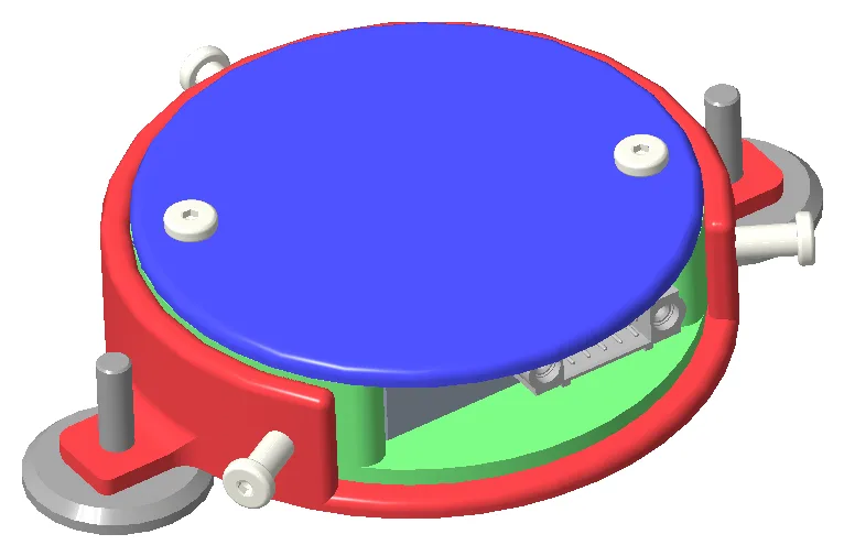
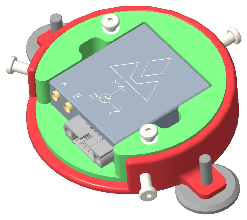
The VNAV Enclosure contains our VNAV sensor, which helps us track our car and is incredibly important to our DAQA team. The main features of this design are the mounting dowels to keep the X-Y position of the sensor repeatable, and a series of screws on the side of the enclosure to allow for adjustable rotation of the sensor to help us align it with antennas on the front and rear of the car.
VNAV Enclosure — AssembledVNAV Enclosure — Lid Removed
Cabling Project
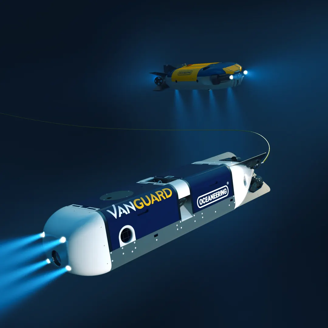
My first project was learning how to use the SolidWorks routing tool to model wire harnesses for all of the telemetry and propulsion systems on a large-scale ROV. This task included documenting the process of using the tool and creating a design history notebook to follow my harnesses as they evolved. I routed over 40 different cables to show our clients how we planned to connect all of our lighting, sensors, manipulators, thrusters, and telemetry together, and I also presented how to model cables more efficiently to our engineering team. The main challenges with this project were ensuring that all my cables maintained the minimum bend radius and minimized any potential for EMI or crosstalk from intersecting cables or a high-power cable next to a signal cable.
Bracket Design and Analysis
I also modeled sensor brackets in SolidWorks and performed hand calcs to validate that my mounting passed the various load cases such as waveslap, transport, and operation. I worked with our analysis team to use their FEA to optimize my design, decreasing the mass of the initial brackets by 37%.
SolidWorks PDM / Excel Tool
One of the main problems that the team was facing was managing all of our part files and assemblies and making sure they followed the naming schematic set in our product breakdown sheet. Since there are infinite ways of naming the files, it was very easy for the thousands of files to get lost, and for no one to be sure what they were actually supposed to be called. I programmed a VBA script to scrape through all of the files related to our master assembly and perform a cross-check with the product breakdown sheet to show what files were named incorrectly and give the correct naming, part description, and part number. This allowed our engineers to make sure all of their projects followed the PBS and my tool became a required step before critical design reviews. Compared to the previous way of searching for parts in the native file explorer or using our part finder, my tool was able to decrease search time by 96% due to automation and more efficient code.